
SUPER LARGE LONG CUSTOM BUILD HYDRAULIC CYLINDER
2023-10-16
About Us
(Summary description)As we know, hydraulic cylinders, also defined as linear motors, is a mechanical device that converts the hydraulic energy of a fluid to mechanical energy. Almost all hydraulic systems ultimately drive a hydraulic cylinder. No matter how accurately the selection of hydraulic unit equipment is made, we get to see them in action only with hydraulic cylinders. Hydraulic cylinders designed and produced without considering certain principles may not perform as desired. This can affect the entire hydraulic system and result in huge financial losses. This writing will address the most common problems that occur during the design and production stages of hydraulic cylinders, explain the issues caused by these problems and point out the solutions and things to take into account.
(Summary description)As we know, hydraulic cylinders, also defined as linear motors, is a mechanical device that converts the hydraulic energy of a fluid to mechanical energy. Almost all hydraulic systems ultimately drive a hydraulic cylinder. No matter how accurately the selection of hydraulic unit equipment is made, we get to see them in action only with hydraulic cylinders.
Hydraulic cylinders designed and produced without considering certain principles may not perform as desired. This can affect the entire hydraulic system and result in huge financial losses.
This writing will address the most common problems that occur during the design and production stages of hydraulic cylinders, explain the issues caused by these problems and point out the solutions and things to take into account.
As we know, hydraulic cylinders, also defined as linear motors, is a mechanical device that converts the hydraulic energy of a fluid to mechanical energy. Almost all hydraulic systems ultimately drive a hydraulic cylinder. No matter how accurately the selection of hydraulic unit equipment is made, we get to see them in action only with hydraulic cylinders.
Hydraulic cylinders designed and produced without considering certain principles may not perform as desired. This can affect the entire hydraulic system and result in huge financial losses.
This writing will address the most common problems that occur during the design and production stages of hydraulic cylinders, explain the issues caused by these problems and point out the solutions and things to take into account.
1. HYDRAULIC CYLINDER PARTS
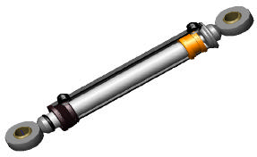
Picture 1. Solid model cylinder
Unless there is special request, the material is of E355 +SR (EN 10305-1) quality. The inner surface of the barrel is honed.
1.2. Tie Rod
Tie rods are usually made of stainless or tempered steels according to C45E (EN 10083-2) and operating conditions. Since the cylinder is in contact with the outside environment during operation, there is corrosion-resistant coating on their outer surfaces.
1.3. Front Cover (Cap)
The cap can be made of cast iron, ductile iron or unalloyed manufacturing steels. It can be connected to the barrel with screws or bolts. In addition to carrying the sealing elements, it also acts as a bearing.
1.4. Piston
The piston can be made of cast iron, ductile iron or unalloyed manufacturing steels. It carries the sealing element that prevents internal leakage. It also acts as a bearing.
1.5. Rear Cover
The material should be of St 52-3 quality for compatibility with the barrel. If unavailable, unalloyed steels with low carbon ratio should be used. It covers the rear of the barrel and carries the connection element.
1.6. Tie Rod End
Although they are ready-made, there are various connection types demanded in machine construction.
1.7. Sealing Elements
To be explained in Section 3.
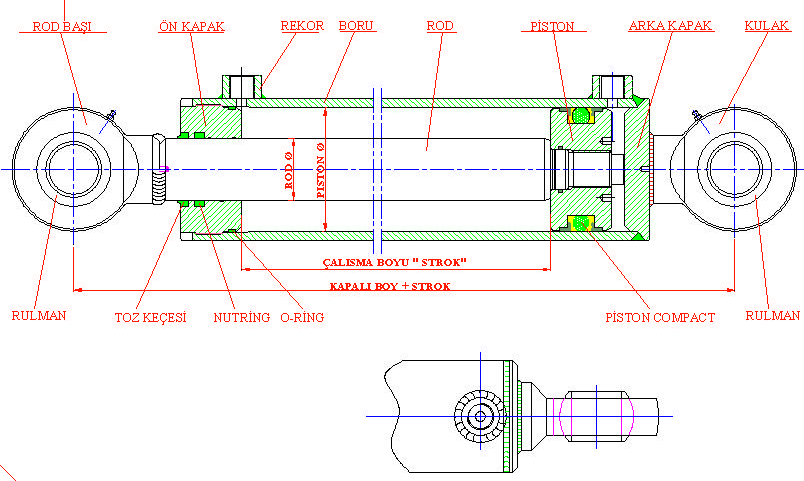
Figure 1. 2D assembly drawing
2. LINEARITY IN HYDRAULIC CYLINDERS
Hydraulic cylinders are complex pieces of equipment consisting of multiple parts. With reciprocating motion, the parts operate on a single connection axis. This is why all parts that make up the cylinder must be positioned on the same axis. Otherwise;
* Differences in axes cause reclined cylinder operation and rapid wear on the seals.
* Different axes also cause cylinder elements to bear undesired loads, shortening the life of the said elements.
* If the cylinder is stronger than the frame connection, it will strain the machine frame and cause frame deformation.
* The system heats up quickly.
* The electric motor and pump become stressed.
* All of this causes unnecessary power losses and efficiency drops.
Now, let's briefly examine the processing methods of the parts that make up the cylinder and the details to be considered.
2.1. Barrel
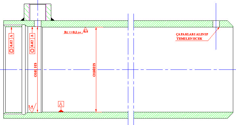
Figure 2. Barrel details
In barrel production, the reference is always the inner diameter of the barrel. All operations on the barrel during production are carried out in consideration of the inner diameter. In addition, if the oil sleeve is welded, this process should be carried out before turning. A good look at the picture shows the size of Ø101, which is 1 mm larger than the diameter of the barrel. This area is the seat of the front cover. If the post-welding ovality has exceeded the stipulated boundaries, it should be processed at once via threading in consideration of the inner diameter of the barrel.
Another point to be considered in processing the size of Ø101 is surface quality. A look at the whole picture
shows that the o-ring, one of the sealing elements, is in this area.
Surface quality and circularity directly affect the service life of the sealing elements. Looking at the diameter of 100 on the picture, it is clear that the desired surface quality is at Rt<= 0.3 µ. This is the surface where the piston seal and bearing elements operate. If the surface quality is poor, it may cause internal leakage in the cylinder and reduce the life of the seal. These pipes are supplied in the market in honed or hone-ready form.
2.2. Tie Rod
The surface, piston and bearing elements operating in the cylinder tie rods should meet the required concentricity tolerances. The bevel displayed at 20° in the picture ensures that the sealing elements pass through without being damaged during assembly. If the tie rod is made of ready-coated rod, its outer surface should be protected during processing. While the tie rod is in the bearing, no sawdust should be allowed between them, and an apparatus should be used to prevent traces during bearing rotation.
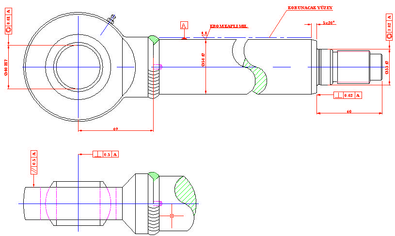
Figure 3.
2.3. Front Cover (Cap)
Connected to the barrel using various methods according to construction principles, the front cover is among the essentials. Since the cover is in static contact with the barrel surface and in dynamic contact with the tie rod surface, any geometric tolerance deviations may place the entire system at risk, no matter how properly the barrel and the tie rod have been produced. This is why concentricity tolerance is very critical in the area bearing the barrel and the area bearing the tie rod. In addition, the perpendicularity tolerance on the face is also critical at the end of the stroke during operation. If there is axial curvature on the face, the piston facing tends to lean against the curved surface due to the pressure at the end of the stroke. By stretching the tie rod to the degree of curvature, undesired additional loads are applied to the bearing elements on the piston in different axes.
Front covers also provide bearing for the sealing elements. The surface quality of the ducts in which the sealing elements are installed directly affects the life of the elements. Pitting in the ducts, and sets and dimensions exceeding the tolerance limits are direct causes of external leakage.
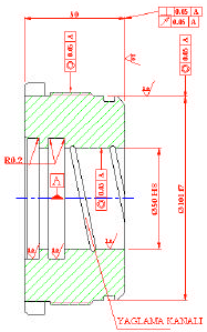
Figure 4.
2.4. Piston
The piston carries sealing elements such as front covers. Since its outer surface moves in the barrel and its inner surface is fixed on the tie rod, any geometric tolerance deviations in the piston may risk the entire system, no matter how properly the barrel and the tie rod have been produced. The issues mentioned for the front cover are also valid for the piston.
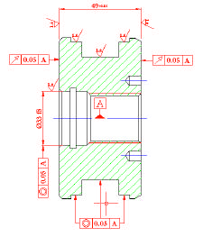
Figure 5.
2.5. Rear Cover
As the element that covers and bears the cylinder's rear connection, the parallelism between the two surfaces and the perpendicularity tolerances of these surfaces in accordance with the shoulder diameter are critical. If tolerance limits are exceeded, the cylinder connection axis may be disrupted, causing undesired loads on the cylinder and the construction, and even prevent proper assembly of the cylinder.
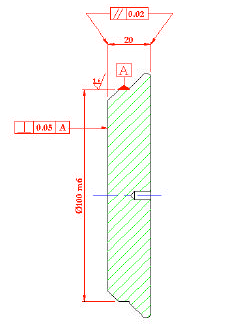
Figure 6.
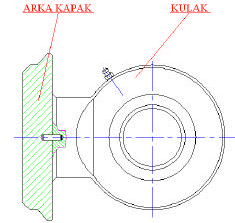
2.6. Tie Rod End and Barrel End
There are hundreds of connection types available depending on the construction. Regardless of the connection type, it should be ensured that machining and welding operations are carried out in a way that will prevent axial deviations during the basic connection. If a welded connection has been deemed necessary and made, the tie rod and sleeve ends can be machined after welding. This type of production reduces the risks. However, processing times are longer and material sizes increase.
Scan the QR code to read on your phone
Related News
Contact Information


Follow Us

Copyright © 2022 Jiangsu YINGNAISI Machinery Manufacturing Co., Ltd. All rights reserved 苏ICP备12047497号-1 Powered by: www.300.cn
 +86-18961135521

 Message